


I've seen the hazard switch trick mentioned a few times recently so I thought I'd post a guide I wrote way back in 2000 (Not very well today and bored so here you go)
Firstly, the obligatory disclaimer
Every effort has been made to ensure that the information contained in this guide is accurate. However the author assumes no responsibility for any errors or omissions. By undertaking anything described in this document you assume full responsibility for any consequences.
And on with the guide, it's intended for the Mk2 but may come in handy for those who've converted a mk1 dash to mk2 and re-loomed...
This is a pretty essential security modification, particularly if your car can be bump started (carb models with mechanical fuel pump). It may seem crazy but if you take out your hazard switch and push it in upside down your ignition will come on, even if you have an immobiliser. (Whether yours stops this problem is dependent on how the installer chose to disable the ignition).
The problem seems to stem from the way Vauxhall wired up the relay for the indicators and hazard switch. There is a loop to allow the hazards to work with or without the ignition and the indicators only with the ignition. It is probably just coincidence that the pins on the switch create a circuit when flipped. To stop the, err, ‘fault’ you need to fit a diode which kills the loop.
So whats a diode ? Its an electronic component that only allows electricity to flow in one direction. In this case we want electricity to flow one way through the switch to the indicator lights but not the other way which powers the ignition.
Read on for instructions... Its better if you can solder or use a decent wire join crimp etc
I borrowed MJ’s GSi to do this tutorial ‘cos I’ve already done my SRi, so thanks for that MJ.
1. Remove the hazard switch. You must switch it on before you pull it out, if you don’t you’ll break it and have a twenty something quid bill - your indicators won’t work without it !
2. Remove the clock. Use a small flat blade screw driver at the back, top left of the clock and it’ll pop out - and no marks on your dash. Remove the instrument shroud, there are four screws holding this - you’ll need a Torx (star) bit / key to remove these.
3. You need to remove the left hand centre vent in order to get at a screw. To remove the vent thread some wire through the vent at the top and pull, the vent will pop out. Picture below shows the switch,clock and instrument shroud removed and also wire threaded through the vent (note: it should be the top of the vent!).
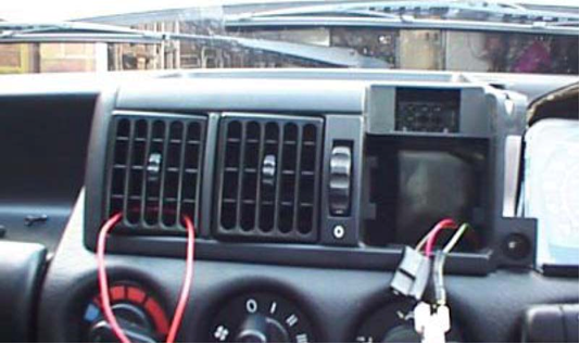
4. Remove the tray that holds the vent and clock etc. There are two Torx screws at the back of the tray and one Philips below the left hand vent. Having removed the vent you should be able to see this - don’t drop it inside the dash when you remove it!
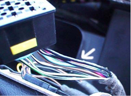
5. Using a screw driver carefully push out the hazard switch connector in the back of the tray. Put the tray out of the way. You now have access to the wires, remove some of the cable wrap. It should look like the picture below:
6. You are interested in the two black wires connected to the same point, indicated by the arrow in the picture above. Cut these wires at about the point shown by the arrow. Strip the ends of both to expose the wire - twist the cable to keep all the strands of copper together. Twist the two wire ends at the connector together and like wise with the other two wire ends.
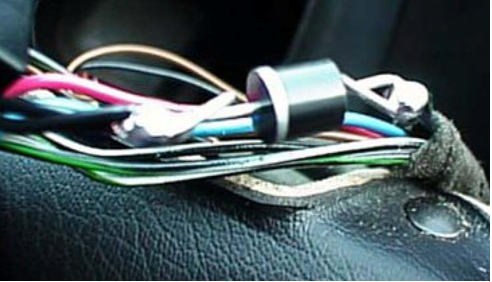
7. Now fit a diode between the wires as shown in the picture below (Part no. 1N5402 Maplin Order No. QL83E). the one listed here is more than adequate, although the one shown is of the ‘I’d like a bloody large diode’ type ! Solder the diode as shown in the picture below noting the orientation of the silver band on the diode (this shows which direction the electricity can flow).
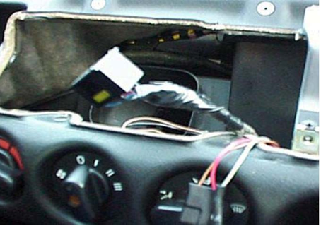
8. Check that your indicators, hazard and dash indicator light all work properly (you’ll need to push the hazard switch into the connector to check this). If its all ok, cool, if not check you’ve got the diode the right way round and that the wires are all connected to it correctly. If its ok, apply some insulating tape to the diode and black wires. Finally tape up the cable bunch as shown below (You can do it a bit neater than this if you like!):
9. Slide the connector into the plastic tray (make sure its the right way up!) and put everything back in the reverse order to taking it out. Job done. If you reverse your switch now you will here your indicator relay ticking fast but your ignition will not come on.
That's it!

 Reply With Quote


