


Today Graeme popped down the road to mine and we had a look at the total closure issue, after a bit of checking his closure module it turned out that things would be pretty straight forward, excluding the time messing with the Toad alarm after completing the job in order to program it to close the windows upon a "arm" command, the wiring itself took no more than an hour to do, for those who wish to read a rough how to, please read on, if you dont want to read it, but just see the proof, scroll down to the end of this post.
These instructions are only intended for a Nova, Due to their "At rest" state
(Before starting work, please read all the steps, The following codes/colours I refer to will be the standard Nova loom ones and I will not be held accountable if you don't follow these instructions properly and injure/maim yourself or set fire to your car)
IF IN ANY DOUBT USE A MULTIMETER FIRST

Now as everyone knows that when the ignition is switched on, that both the feeds from each switch go live to the to the motors, and then require a posi feed cut and swapped to negative, If im already starting to loose you then simpily if you remove both window switches from their holder you will see 4 wires on the back of each, the important ones are the two blue ones
Blue
Blue with Red trace
(One only to each switch)
These are the feeds to the motors you will need to cut, now before you go cutting things, its best to double check that it is the right wire, so after you remove the centre console, switches and loom so that it is loose, reconnect the switches and...
1. posistion both windows halfway down
2. turn off the ignition and remove the keys (so there is no power going to the switches/windows)
3. disconnect the two 4pin plugs from both of the window switches to loom (lift up the tab to seperate)
4. make a 2-3 inch fly lead to connect to the yellow or *yellow/red *(dependant on which plug you test) and loop this to the brown of that 4 pin socket, which is Ground
5.with a suitable guage'd 6 foot length of wire, insert one end into the back of the blue or blue/red cable pin (relative to the same socket that you just used for above) on the loom socket and then touch the other end to your posi terminal on the battery
If you have done it right, the window will roll up, if not it will roll down, hence leaving the window in the middle at the start, if it does roll down then the wire you will need to try the other window feed wire which is yellow + yellow/red which is on the furthest pin from the blue ones, but also test this to make sure that it is by swapping the fly lead to blue and the posi feed to yellow.
Note*(the two inner ones are the posi (ignition switched) and ground feeds to the circuit)
Now you have identified which wire needs to go live to roll the windows up and with also leaving an inch or two wire before the connector, cut the identified feed wire in half on the loom side of the 4 pin plugs, do not cut the switch side wires, if you cut it on the switch side,
1. you wont get the switches back in after
2. if you ever need to swap out the switches you will need to rewire it all again
3. there wont be enough spare wire to get it under the console when your done
now you should have 2 wires in half, (hopefully blue ones)
now the next bit may get a little hazy depending on your make and model of window closure unit, the one we used was a two window version of the Falcon security one, this had 2 pairs of wires to feed the circuit,
(Falcon only) these were paired as
Blue & Green (one window motor)
Blue/white & Green/white (the other window motor)
hopefully you can tell from your schematic as to their motor pairings you need, on the falcon diagram there was one from each of the pairs that was shown to go to the motor and one to the switch, these pairs will connect with the wires you cut in an order
EG
the 2 wires cut were blue and blue/red trace
solid blue would be bundled with both the solid blue and solid green from the falcon module
trace wires would also then be bundled accordingly
and as per your units schematics, one of those wires from each pair from the module is only intended to go to the motor, and the other is only to be connected to the switch
now you have found the motor supply from the module, connect that to the wire from its intended bundle and connect it to the blue loom wire that is NOT still connected to the 4 pin plug, then take the switch supply from the controller and connect it to the other half of the blue wire on the 4 pin plug side.
now you have one window hooked up, you may want to check its working, so connect the power to the module as per instructions, and if you have one, hook up the Ignition ACC+ wire to either of the black wires on the back of the 4 pin connector for the switches, re-attach the switch for the side you have just wired up, turn on the ignition and wind that window halfway down again.
now dependant if your alarm is negative or positive signal for the window module, put that wire from the module to any ground or posi feed to start the auto close module.
(fingers crossed that all's well and it goes up!)
...its ok?, now just do what you did with connecting the wires up before and do that again on the other switch set.
Check it again and provided it works, finalize the connections, make them all safe, now you know that the module works go ahead and hook it up to the alarm unit, (If you hook it up to the alarm before any testing chances are if you have a fault, it will be harder to find at this late stage)
now you may have 2 triggers + & - ones, now check your alarm manual to see what signal it provides upon your request/system arm, it may be a pull to ground, or set to live, (usually its to ground), connect that wire up to the modules relevant trigger wire, make the joint safe, wind both windows halfway down, get out and test the alarm side.
That's your lot.
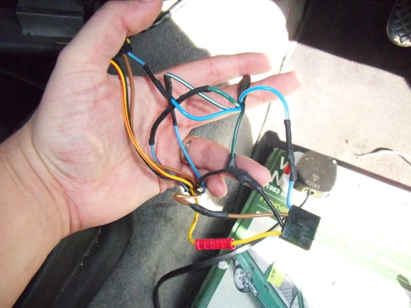
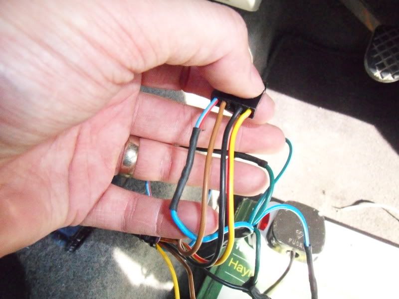
Here's some photos of the joints we did and a video of the unit actually working!
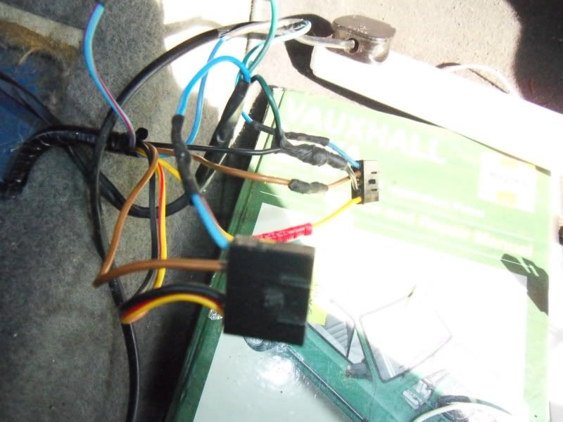
The crimp connector was already there i must add
VIDEO
http://s1102.photobucket.com/albums/...t=7ac507f3.mp4
 Menu
Menu